In this article, we will be consolidating the matrix and camera knowledge from
the previous article into the new tdogl::Camera class, which will be a
first-person shooter type of camera. Then, we will connect the camera to
keyboard and mouse input, so we can move within the 3D scene and look around.
This will involve learning a bit of vector math. We will also learn about
inverting matrices, which was not mentioned in the previous article.
Accessing The Code
Download all the code as a zip from here: https://github.com/tomdalling/opengl-series/archive/master.zip
All the code in this series of articles is available from github: https://github.com/tomdalling/opengl-series. You can download a zip of all the files from that page, or you can clone the repository if you are familiar with git.
This article builds on the code from the previous article.
The code for this article can be found in the
source/04_camera
folder. On OS X, open the opengl-series.xcodeproj file in the
root folder, and select the target that corresponds with this article. On
Windows, open the opengl-series.sln file in Visual Studio 2013,
and open the project that corresponds with this article.
The project includes all of its dependencies, so you shouldn't have to install or configure anything extra. Please let me know if you have any issues compiling and running the code.
Vector Theory
Just when you thought the mathematical theory lesson was over, after learning matrix theory in the previous article, here comes the next instalment: vectors. A decent understanding of vectors is fundamental to 3D programming. When we get to the code later, we will be using vectors to move the camera in various different directions using the keyboard.
In 3D (and also 2D), vectors are used to represent a few different things, such as:
- Position (i.e. coordinates)
- Displacement (e.g. movement)
- Direction (e.g. north, south, up, down, etc.)
- Velocity (e.g. the speed and direction of a car)
- Acceleration (e.g. gravity)
You may have noticed that the above concepts are usually implemented in physics engines. We will not be implementing any physics in this article, but a good understanding of vectors is the first step towards implementing some physics.
To use a pseudo-mathematical sort of definition, a vector is a direction with a magnitude.
So, what is a vector? To use a pseudo-mathematical sort of definition, a vector is a direction with a magnitude. A vector can point in any direction. It can be up, down, left, right, towards the donut shop, north, south-south west, etc. Any direction you can point your finger is a valid direction for a 3D vector. The other part of a vector, the magnitude, is the length or size of the vector.
The easiest way to visualise a vector is to draw it. Vectors are typically drawn as arrows. The arrow head tells you the direction of the vector, and the length of the arrow is the magnitude. The illustrations in this article will be of 2D vectors, but the theory applies to both 2D and 3D vectors.
Below are a few examples of vectors used to represent different concepts.
| Direction | Magnitude | Represents | |
|---|---|---|---|
| 5km north | North | 5km | Location |
| 10cm above your head | Up (above your head) | 10cm | Location |
| Driving at 50km/hour towards the lake | Towards the lake | 50km/hour | Velocity |
| Earth’s gravity pulls at 9.8m/s2 | Towards the earth’s center of mass | 9.8m/s2 | Acceleration |
When it comes to programming, a vector is just an array of numbers. Each number is a "dimension" of the vector. For example, a three-dimensional (3D) vector is an array of three numbers.
When it comes to programming, a vector is just an array of numbers. Each number
is a “dimension” of the vector. For example, a three-dimensional (3D) vector is
an array of three numbers, a 2D vector is an array of two numbers, and so on.
Because we’re working in 3D, we will mostly be dealing with 3D vectors, but we
will also need 4D vectors in some situations. Whenever I say “vector,” I mean a
3D vector. We are using GLM as our vector math library, so the 2D, 3D, and 4D
vector types are glm::vec2, glm::vec3, and glm::vec4, respectively.
The three dimensions of a 3D vector are the X, Y, and Z values.
It is easy to see how a 3D vector is used to represent a vertex, a coordinate, or a position. The three dimensions of a 3D vector are the X, Y, and Z values. When a vector represents a position, the direction and magnitude are measured from the origin (coordinate (0,0,0)). For example, if an object has the XYZ coordinate of (0,2,0), then the magnitude is 2, and the direction is “up the Y axis.”
Vector Negation
When you negate a vector the magnitude stays the same, but the direction becomes the opposite of what it used to be.
When you negate a vector – that is, when you make a vector negative – the magnitude stays the same, but the direction becomes the opposite of what it used to be.
For example:
-A = 5km south
We will be using vector negation to calculate the direction to the left of the camera, based on the direction to the right. Something like this:
glm::vec3 rightDirection = gCamera.right();
glm::vec3 leftDirection = -rightDirection; //vector negation
Scalar Multiplication
When you multiply a vector by a single number, the result is a new vector with the same direction, but the magnitude has been multiplied by the single number.
When you multiply a vector by a single number, the result is a new vector with the same direction, but the magnitude has been multiplied by the single number. The single number is called a “scalar,” which is why this is called “scalar multiplication.”
For example:
0.5 × A = 2.5km north
2 × A = 10km north
We will be using scalar multiplication to calculate the displacement of the cameras position based on the “move speed” of the camera – something like this:
const float moveSpeed = 2.0; //units per second
float distanceMoved = moveSpeed * secondsElapsed;
glm::vec3 forwardDirection = gCamera.forward();
glm::vec3 displacement = distanceMoved * forwardDirection; //scalar multiplication
Vector Addition
Vector addition is most easily understood by looking at a graphical representation in 2D. To add vectors together, place them head (arrow end) to tail (non-arrow end). Order is not important. The result of the addition is: a vector from the tail of the first vector to the head of the last vector.
Notice how the magnitude (length) and direction of the vectors never changes, even though they appear in different positions. Remember that vectors have a direction and a magnitude only. They don’t have a start point, so they can be visually represented at different positions and still be identical.
For example:
A = 1km north
B = 1km east
A + B = 1.41km northeast
Vector subtraction is the same as adding a negative vector, for example:
A = 1km north
B = 1km east
A - B = 1.41km northwest
A + (-B) = 1.41km northwest
We will be using vector addition to calculate the new position of the camera, after it has been displaced (moved). Something like this:
glm::vec3 displacement = gCamera.forward() * moveSpeed * secondsElapsed;
glm::vec3 oldPosition = gCamera.position();
glm::vec3 newPosition = oldPosition + displacement; //vector addition
gCamera.setPosition(newPosition);
Unit Vectors
Unit vectors are vectors with a magnitude equal to one. They are often used to represent a direction.
Unit vectors are vectors with a magnitude equal to one. They are often used to represent a direction.
It doesn’t really matter what the magnitude is when a vector is only used to represent a direction. However, if the magnitude is equal to one, it allows us to do calculations more easily.
When you perform scalar multiplication on a unit vector, the direction stays the same, but the magnitude will be equal to the scalar. So if you multiply a unit vector by five, then the magnitude of the resulting vector is also five. If you multiply by 123, the magnitude will be 123. It basically allows us to set the exact magnitude of a vector, without affecting the direction.
This allows us to do things like moving the camera 12 units to the left. We take the unit vector for the left direction, set the magnitude to 12 using scalar multiplication, then use that to calculate the new position. The code would look something like this:
// `gCamera.right()` returns a unit vector, therefore `leftDirection` will also be a unit vector.
// Negation only affects the direction, not the magnitude.
glm::vec3 leftDirection = -gCamera.right();
//`displacement` will have a magnitude of 12
glm::vec3 displacement = leftDirection * 12;
//`newPosition` will be 12 units to the left of `oldPosition`
glm::vec3 newPosition = oldPosition + displacement;
Any vector can be turned into a unit vector. This operation is called normalisation. This is how to normalise a vector using GLM:
glm::vec3 someRandomVector = glm::vec3(123,456,789);
glm::vec3 unitVector = glm::normalize(someRandomVector);
The tdogl::Camera Class
Congratulations if you’ve made it this far! You now understand enough about vectors to get into the code.
The interface for the tdogl::Camera class is available here,
and the implementation is here.
As we learnt in the previous article, a camera in OpenGL can be represented as
a matrix. The purpose of the tdogl::Camera class is to create this matrix
based on a bunch of attributes, such as:
- Camera position
- Camera orientation (direction)
- Zoom (field of view)
- Maximum and minimum viewing distances (near and far planes)
- The aspect ratio of the viewport/window
There are setters and getters for each of the attributes above. These attributes were explained in the previous article.
Let’s look at the matrix and orientation methods to see how all of these
attributes are combined into a single matrix.
glm::mat4 Camera::matrix() const {
    glm::mat4 camera = glm::perspective(_fieldOfView, _viewportAspectRatio, _nearPlane, _farPlane);
    camera *= orientation();
    camera = glm::translate(camera, -_position);
    return camera;
}

glm::mat4 Camera::orientation() const {
    glm::mat4 orientation;
    orientation = glm::rotate(orientation, _verticalAngle, glm::vec3(1,0,0));
    orientation = glm::rotate(orientation, _horizontalAngle, glm::vec3(0,1,0));
    return orientation;
}
As you can see, the final camera matrix is a combination of four different transformations. In order, the transformations are:
- Translate, based on the position of the camera
- Rotate, based on the horizontal (left/right) angle of the camera
- Rotate, based on the vertical (up/down) angle of the camera
- Perspective, based on the field of view, near plane, far plane, and aspect ratio.
If the order looks reversed to you, then remember that matrix multiplication works from right to left – or, in the code above, bottom to top.
Notice that the translation uses the negated position of the camera. Again, remember the previous article, where it explains that instead of moving the camera forward we would pull the whole 3D scene backward. The vector negation will reverse the direction, so “forward” will become “backward.”
The tdogl::Camera class also has methods that return directions as unit
vectors: up, right and forward. We need to know these directions in order
to move the camera with the keyboard.
Inverting the Camera Orientation Matrix
Let’s have a look at the implementation of the tdogl::Camera::up method,
because it contains two things that we haven’t come across before.
glm::vec3 Camera::up() const {
    glm::vec4 up = glm::inverse(orientation()) * glm::vec4(0,1,0,1);
    return glm::vec3(up);
}
An inverse matrix is a matrix that does the *exact opposite* of another matrix, which means it can undo the transformation that the other matrix produces.
The first thing we will look at is the use of glm::inverse. From the last
article, we know that matrices transform coordinates. In certain situations, we
also want to “untransform” coordinates. That is, we want to take a transformed
coordinate and calculate what it used to be, before it was transformed by
matrix multiplication. To do this, we need to calculate the inverse of the
matrix. An inverse matrix is a matrix that does the exact opposite of another
matrix, which means it can undo the transformation that the other matrix
produces. For example, if matrix A rotates 90° around the Y axis, then
the inverse of matrix A will rotate -90° around the Y axis.
When the direction of the camera changes, so does the “up” direction. For example, imagine that there is an arrow pointing out of the top of your head. If you rotate your head to look down at the ground, then the arrow tilts forward. If you rotate your head to look up at the sky, the arrow tilts backwards. If you look straight ahead, then your head is completely “unrotated,” so the arrow points directly upwards. The way we calculate the up direction of the camera is by taking the “directly upwards” unit vector (0,1,0) and “unrotate” it by using the inverse of the camera’s orientation matrix. Or, to explain it differently, the up direction is always (0,1,0) after the camera rotation has been applied, so we multiply (0,1,0) by the inverse rotation, which gives us the up direction before the camera rotation was applied.
(0,1,0) is a unit vector, and when you rotate a unit vector the result will
still be a unit vector. If the result was not a unit vector, we would have to
use glm::normalize on the return value.
The same trick is used to calculate the forward and right directions of the
camera.
You may have noticed that it uses a 4D vector – a glm::vec4. As explained in
the last article, 4x4 matrices (glm::mat4) require 4D vectors for matrix
multiplication – using a glm::vec3 will result in a compile error. The
way we get around this is by turning the 3D vector (0,1,0) into the 4D vector
(0,1,0,1), then we do the matrix multiplication, then we convert the 4D vector
back into 3D before returning it.
Integrating the tdogl::Camera Class
Now we are ready to actually use the tdogl::Camera class.
In the previous article, we had separate shader variables for the projection
matrix and the camera matrix. In this article, tdogl::Camera combines both
matrices, so let’s remove the projection shader variable and just use the
camera variable. This is the updated vertex shader:
#version 150

uniform mat4 camera;
uniform mat4 model;

in vec3 vert;
in vec2 vertTexCoord;

out vec2 fragTexCoord;

void main() {
    // Pass the tex coord straight through to the fragment shader
    fragTexCoord = vertTexCoord;

    // Apply all matrix transformations to vert
    gl_Position = camera * model * vec4(vert, 1);
}
Now we will integrate tdogl::Camera into the code in main.cpp.
Let’s include the class header:
#include "tdogl/Camera.h"
And declare the camera as a global:
tdogl::Camera gCamera;
In the previous article, the camera and projection matrices never changed, so
we set them once in the LoadShaders function. The camera matrix will change
in this article, because we will be controlling it with the mouse and keyboard,
so we will have to set the camera matrix every frame inside the Render
function. First, let’s remove the old code from LoadShaders:
static void LoadShaders() {
    std::vector<tdogl::Shader> shaders;
    shaders.push_back(tdogl::Shader::shaderFromFile(ResourcePath("vertex-shader.txt"), GL_VERTEX_SHADER));
    shaders.push_back(tdogl::Shader::shaderFromFile(ResourcePath("fragment-shader.txt"), GL_FRAGMENT_SHADER));
    gProgram = new tdogl::Program(shaders);

    // the commented-out code below was removed
    /*
    gProgram->use();

    //set the "projection" uniform in the vertex shader, because it's not going to change
    glm::mat4 projection = glm::perspective<float>(50.0, SCREEN_SIZE.x/SCREEN_SIZE.y, 0.1, 10.0);
    //glm::mat4 projection = glm::ortho<float>(-2, 2, -2, 2, 0.1, 10);
    gProgram->setUniform("projection", projection);

    //set the "camera" uniform in the vertex shader, because it's also not going to change
    glm::mat4 camera = glm::lookAt(glm::vec3(3,3,3), glm::vec3(0,0,0), glm::vec3(0,1,0));
    gProgram->setUniform("camera", camera);

    gProgram->stopUsing();
    */
}
And let’s set the camera shader variable inside of Render:
// draws a single frame
static void Render() {
    // clear everything
    glClearColor(0, 0, 0, 1); // black
    glClear(GL_COLOR_BUFFER_BIT | GL_DEPTH_BUFFER_BIT);

    // bind the program (the shaders)
    gProgram->use();

    // set the "camera" uniform
    gProgram->setUniform("camera", gCamera.matrix());
The call to gCamera.matrix() returns a glm::mat4, and the setUniform
method uses glUniformMatrix4fv to set the camera matrix uniform variable in
the vertex shader.
Let’s set the initial position of the camera and the aspect ratio of the window
inside of AppMain.
gCamera.setPosition(glm::vec3(0,0,4));
gCamera.setViewportAspectRatio(SCREEN_SIZE.x / SCREEN_SIZE.y);
For all the other properties of the camera, we will just use the default values.
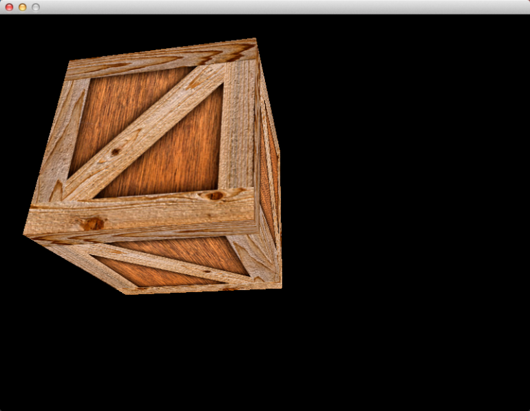
If you run the program now, you should see the spinning cube that we made in the previous article. The last step is to make the camera controllable via the keyboard and mouse.
Keyboard Input
Let’s do the keyboard controls first. Every time we update the scene, we will
check if the ‘W’, ‘A’, ‘S’, or ‘D’ keys are down, and move the camera a little
bit. The function glfwGetKey will return a boolean indicating whether a key
is held down or not. The new Update function looks like this:
// update the scene based on the time elapsed since last update
void Update(float secondsElapsed) {
    //rotate the cube
    const GLfloat degreesPerSecond = 180.0f;
    gDegreesRotated += secondsElapsed * degreesPerSecond;
    while(gDegreesRotated > 360.0f) gDegreesRotated -= 360.0f;

    //move position of camera based on WASD keys
    const float moveSpeed = 2.0; //units per second
    if(glfwGetKey(gWindow, 'S')){
        gCamera.offsetPosition(secondsElapsed * moveSpeed * -gCamera.forward());
    } else if(glfwGetKey(gWindow, 'W')){
        gCamera.offsetPosition(secondsElapsed * moveSpeed * gCamera.forward());
    }
    if(glfwGetKey(gWindow, 'A')){
        gCamera.offsetPosition(secondsElapsed * moveSpeed * -gCamera.right());
    } else if(glfwGetKey(gWindow, 'D')){
        gCamera.offsetPosition(secondsElapsed * moveSpeed * gCamera.right());
    }
}
Rotating the cube is from the previous article, so we’ll ignore that.
Let’s have a closer look at what happens when the S key is held down:
gCamera.offsetPosition(secondsElapsed * moveSpeed * -gCamera.forward());
There is a lot happening on that single line, so let’s rewrite it to understand
it better, in a new function called MoveCameraBackwards.
void MoveCameraBackwards(float secondsElapsed) {
    //TODO: finish writing this function
}
Backwards is a direction, so it will be represented as a unit vector. There is
no method called backward in the camera class, but there is a method called
forward. Backward is the opposite direction of forward, so if we negate the
forward unit vector, we get the backward unit vector.
void MoveCameraBackwards(float secondsElapsed) {
    //`direction` is a unit vector, set to the "backwards" direction
    glm::vec3 direction = -gCamera.forward();

    //TODO: finish writing this function
}
Next, we have to know how far to move the camera. We have the speed that the
camera is moving, in the moveSpeed constant. We also have the amount of time
that has elapsed since the last frame, in the argument secondsElapsed which
comes from the Update function. Multiplying these two values will give us the
total distance to move the camera.
void MoveCameraBackwards(float secondsElapsed) {
    //`direction` is a unit vector, set to the "backwards" direction
    glm::vec3 direction = -gCamera.forwards();

    //`distance` is the total distance to move the camera
    float distance = moveSpeed * secondsElapsed;

    //TODO: finish writing this function
}
Now that we know the distance and direction of the movement, we can make a
displacement vector. The magnitude will be distance, and the direction comes
from direction. Because direction is a unit vector, we can use scalar
multiplication to set the magnitude.
void MoveCameraBackwards(float secondsElapsed) {
    //`direction` is a unit vector, set to the "backwards" direction
    glm::vec3 direction = -gCamera.forwards(); //vector negation

    //`distance` is the total distance to move the camera
    float distance = moveSpeed * secondsElapsed;

    //`displacement` is a combination of `distance` and `direction`
    glm::vec3 displacement = distance * direction; //scalar multiplication

    //TODO: finish writing this function
}
Lastly, we have to move (a.k.a. displace) the original position of the camera.
This is done by vector addition. The basic formula is newPosition =
oldPosition + displacement.
void MoveCameraBackwards(float secondsElapsed) {
    //`direction` is a unit vector, set to the "backwards" direction
    glm::vec3 direction = -gCamera.forwards(); //vector negation

    //`distance` is the total distance to move the camera
    float distance = moveSpeed * secondsElapsed;

    //`displacement` is a combination of `distance` and `direction`
    glm::vec3 displacement = distance * direction; //scalar multiplication

    //change the position of the camera
    glm::vec3 oldPosition = gCamera.position();
    glm::vec3 newPosition = oldPosition + displacement; //vector addition
    gCamera.setPosition(newPosition);
}
Done! The MoveCameraBackwards function does exactly the same thing as the
single line:
gCamera.offsetPosition(secondsElapsed * moveSpeed * -gCamera.forward());
The offsetPosition method does the vector addition, and it takes a
displacement vector as its argument. Let’s keep using the single line instead
of the MoveCameraBackwards function, because less code is better.
All the other keys work in exactly the same way, except the direction is different. While we’re at it, let’s make the Z and X keys move the camera up and down.
if(glfwGetKey(gWindow, 'Z')){
    gCamera.offsetPosition(secondsElapsed * moveSpeed * -glm::vec3(0,1,0));
} else if(glfwGetKey(gWindow, 'X')){
    gCamera.offsetPosition(secondsElapsed * moveSpeed * glm::vec3(0,1,0));
}
Notice how it uses the vector (0,1,0) instead of gCamera.up(). Remember that
the “up” direction will change depending on the direction that the camera
looks. If the camera looks at the ground, the “up” direction will be tilted
forwards. If the camera looks at the sky, the “up” direction will be tilted
backwards. That’s not exactly the behaviour that we want, so we use the
“directly up” direction (0,1,0) instead, which does not depend on the direction
that camera is looking.
If you run the program now, you can use the W, A, S, D, X, and Z keys to move forward, left, backwards, right, up and down, respectively. You still can’t change the direction that the camera is looking, because that will be controlled by the mouse.
Mouse Input
At the moment, our window doesn’t capture the mouse. That is, you can still see the mouse moving over the top of the window. We want the mouse to be invisible, and we also don’t want it to go outside of the window while we’re using it to look around. To achieve this, we have to change some of the GLFW settings.
Before we capture the mouse, let’s make the escape key quit the program. We
won’t be able to click the close button anymore, because the mouse will be
invisible and can’t leave the window. Let’s do this at the bottom of the main
loop inside AppMain:
// run while the window is open
double lastTime = glfwGetTime();
while(!glfwWindowShouldClose(gWindow)){
    // process pending events
    glfwPollEvents();

    // update the scene based on the time elapsed since last update
    double thisTime = glfwGetTime();
    Update((float)(thisTime - lastTime));
    lastTime = thisTime;

    // draw one frame
    Render();

    // check for errors
    GLenum error = glGetError();
    if(error != GL_NO_ERROR)
        std::cerr << "OpenGL Error " << error << std::endl;

    //exit program if escape key is pressed
    if(glfwGetKey(gWindow, GLFW_KEY_ESCAPE))
        glfwSetWindowShouldClose(gWindow, GL_TRUE);
}
Now we can capture the mouse. Just after we open the window with
glfwCreateWindow, do this:
// GLFW settings
glfwSetInputMode(gWindow, GLFW_CURSOR, GLFW_CURSOR_DISABLED);
glfwSetCursorPos(gWindow, 0, 0);
This makes the mouse invisible and moves it to the pixel coordinate $$(0,0)$$.
Inside Update we will get the position of the mouse, update the camera, then
set the mouse back to $$(0,0)$$ again. This is an easy way to see how far the mouse
has moved every frame, while also stopping the mouse from leaving the window.
Add this code to the bottom of the Update function:
//rotate camera based on mouse movement
const float mouseSensitivity = 0.1f;
double mouseX, mouseY;
glfwGetCursorPos(gWindow, &mouseX, &mouseY);
gCamera.offsetOrientation(mouseSensitivity * (float)mouseY, mouseSensitivity * (float)mouseX);
glfwSetCursorPos(gWindow, 0, 0); //reset the mouse, so it doesn't go out of the window
The mouse coordinates are in pixels, but the camera direction is based on two
angles. This is why we use the mouseSensitivity constant to convert pixels to
angles. The larger the mouse sensitivity, the faster the camera direction
changes. The smaller the sensitivity, the slower the direction changes. With
the sensitivity set to 0.1f, the camera will rotate 1° for every 10 pixels
of mouse movement.
The offsetOrientation method is sort of like the offsetPosition method we
saw earlier. It will displace the direction of the camera by updating the
horizontal and vertical angles.
Ok! We are basically finished. If you run the program now, you can fly around and look in almost any direction. The animated rotation of the cube can be a bit disorientating while flying around, so you might want to disable that.
Controlling Field of View With Mouse Wheel
As the icing on the cake, let’s make scrolling the mouse/touchpad affect the camera zoom by changing the field of view. Field of view was explained in the previous article.
We will use the same trick that we used for the mouse position, and reset the scroll amount to zero every frame. First, we make a global that holds the scroll amount:
double gScrollY = 0.0;
To receive scroll input using GLFW, we first have to create a callback:
// records how far the y axis has been scrolled
void OnScroll(GLFWwindow* window, double deltaX, double deltaY) {
  gScrollY += deltaY;
}
Then we register the callback with GLFW in AppMain like this:
glfwSetScrollCallback(gWindow, OnScroll);
Now, for every frame we render, we use the gScrollY value to change the field of view.
This happens at the bottom of the Update function:
const float zoomSensitivity = -0.2f;
float fieldOfView = gCamera.fieldOfView() + zoomSensitivity * (float)gScrollY;
if(fieldOfView < 5.0f) fieldOfView = 5.0f;
if(fieldOfView > 130.0f) fieldOfView = 130.0f;
gCamera.setFieldOfView(fieldOfView);
gScrollY = 0;
The zoomSensitivity constant works the same way as the mouseSensitivity
constant. The field of view can be anything between 0° and 180°, but if
you get too close to those limits then the 3D scene looks very weird, so we
restrict the value to between 5° and 130°. Just like we did with the
mouse position, we set gScrollY = 0 after every frame.
Future Article Sneak Peek
In the next article, we will restructure the code into a very primitive “engine.” We will split the code into assets (a.k.a. resources) and instances, like a typical 3D engine, and make a 3D scene out of multiple, slightly-different wooden crates.
Additional Resources
- The vector math chapter of Learning Modern 3D Graphics Programming by Jason L. McKesson
- Vector maths – a primer for games programmers
- Basic 3D Math: Vectors by Egon Rath
- Wikipedia article on vectors, which isn’t very beginner-friendly
- The GLFW guides and references.
- If you know of any beginner-friendly articles about vectors, please send them to me so that I can add them here.