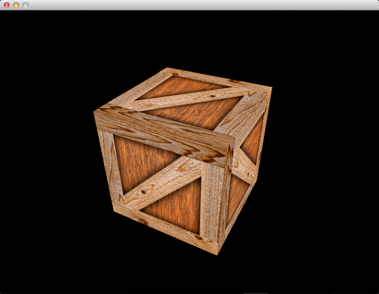
In this article, we will replace our immobile 2D triangle with a spinning 3D cube. The end result will look like this:
Now that we’re finally getting something interesting on the screen, I can include more pictures! An album of animated gifs is available here: http://imgur.com/a/x8q7R
In order to make this spinning cube, we will learn a bit about matrix math, and how it is used to create perspective projections, rotation, translation, and the concept of a “camera.” We will also learn about depth buffering, and why it is necessary. We will also see how a typical 3D application implements changes over time, such as animation.
Accessing The Code
Download all the code as a zip from here: https://github.com/tomdalling/opengl-series/archive/master.zip
All the code in this series of articles is available from github: https://github.com/tomdalling/opengl-series. You can download a zip of all the files from that page, or you can clone the repository if you are familiar with git.
This article builds on the code from the previous article.
The code for this article can be found in the
source/03_matrices
folder. On OS X, open the opengl-series.xcodeproj file in the
root folder, and select the target that corresponds with this article. On
Windows, open the opengl-series.sln file in Visual Studio 2013,
and open the project that corresponds with this article.
The project includes all of its dependencies, so you shouldn't have to install or configure anything extra. Please let me know if you have any issues compiling and running the code.
Matrix Theory
This article is mostly about using matrices in 3D, so let’s start with a bit of matrix theory before getting into the code. I’m not going to focus much on the math, as there are lots of good online resources for that. We are using GLM to perform all the math for us. I will be focusing on what matrices can do for us in our 3D application.
Matrices are used to transform 3D coordinates.
Matrices are used to transform 3D coordinates. Possible transformations include (click for animated example):
- Rotation
- Scaling (growing and shrinking)
- Translation (moving)
- Perspective/orthogonal projection (explained later)
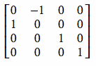
A matrix is a grid/table of numbers, like this:
The plural of matrix is “matrices” (pronounced “mey-tri-seez”). For example, “I have one matrix” and “I have have two matrices.”
Different numbers produce different types of transformations. The matrix above will rotate coordinates 90° around the Z axis. We will be using GLM to create our matrices, so you do not need to understand how to calculate the numbers.
Matrices can have any number of rows and columns, but for 3D transformations we need a 4×4 matrix like the one shown above. Whenever I say “matrix,” I mean a 4×4 matrix.
When it comes to code, a matrix is usually represented as an array of floats.
We will be using the glm::mat4 class to represent a 4×4 matrix.
matrix × matrix = combined matrix
matrix × coord = transformed coord
The two most important matrix operations to understand are:
- matrix × matrix = combined matrix
- matrix × coordinate = transformed coordinate
Matrix × Matrix
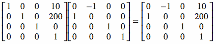
When you multiply two matrices, the product is a new matrix that does both of the transformations.
For example, if you multiply a rotation matrix by a translation matrix, the result is a “combined” matrix that does both rotation and translation. Below is an example of this type of matrix multiplication:
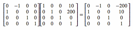
Unlike normal multiplication, order is important in matrix multiplication.
Unlike normal multiplication, order is important in matrix multiplication. For
example, if A and B are matrices, then A × B is not necessarily
equal to B × A. The multiplication below is the same as the one above,
but with the order changed:
Notice how the result is different if the order is changed. The animations below show why order is important. They perform the same transformations, but in a different order. The transformations are: a translation up the Y axis, and a 45° rotation.
![]()
![]()
If, while you are coding, you see that a transformation is wrong, then go back and check that your matrix multiplication is in the correct order.
Matrix × Coordinate
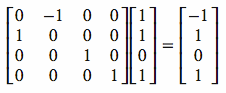
When you multiply a matrix by a coordinate, the product is a new coordinate that has the transformation applied to it.
For example, if you take the rotation matrix above and multiply it by the coordinate (1,1,0) the result is the “transformed” coordinate (-1,1,0). The transformed coordinate is the original coordinate after being rotated 90° around the Z axis. Below is an example of this type of matrix multiplication:
Why We Use 4D Coordinates
You will notice that the coordinates above are 4D, not 3D. They are in the format:

We need to use 4D coordinates because 4x4 matrices require them in order to do matrix multiplication.
So why are we using 4D coordinates? Well, we require 4x4 matrices in order to do all the 3D transformations that we need. However, matrix multiplication requires that the number of columns in the left-hand side is equal to the number of rows on the right-hand side. This means that a 4x4 matrix can not be multiplied with a 3D coordinate, because the matrix has four columns but the coordinate only has three rows. We need to use 4D coordinates because 4x4 matrices require them in order to do matrix multiplication.
Some transformations, such a rotation and scaling, only require a 3x3 matrix. For those transformations, we don’t need 4D coordinates because 3D will work. However, translation requires at least a 4x3 matrix, and perspective projection requires a 4x4 matrix, and we need both of those, so we are forced to use 4D.
These are called homogeneous coordinates. In a later article, when we cover directional lighting, we will learn about what the ‘W’ dimension actually represents. At this point, however, we only need to know how to convert from 3D to 4D. When you convert a 3D coordinate into 4D, always set the 4th dimension, ‘W’, to 1. For example, the coordinate (22,33,44) will look like:

When you convert a 4D coordinate back to 3D, if the ‘W’ dimension is still set to 1 then you can just ignore it and use the X, Y and Z values like you normally would. If you find that your ‘W’ value has changed to something other than 1, well… you’re either doing something advanced, or you have a bug.
Making A Cube
The first change to the code will be to replace the triangle from the previous article with a cube.
I’ve made the cube out of triangles, by using two triangles on each of the six
sides. In older versions of OpenGL, we could have used one square (GL_QUADS)
per side instead of two triangles, but GL_QUADS have been removed from modern
versions of OpenGL. The X, Y and Z coordinates will range from -1 to +1, which
means the cube will be two units wide, and the center of the cube will be the
origin (the origin is coordinate (0,0,0)). We will use one 256×256
texture for all sides of the cube. The data is going to be in the same format
as the last article, so we won’t need to change much. Here is the new data for
the cube:
GLfloat vertexData[] = {
    //  X     Y     Z       U     V
    // bottom
    -1.0f,-1.0f,-1.0f,   0.0f, 0.0f,
     1.0f,-1.0f,-1.0f,   1.0f, 0.0f,
    -1.0f,-1.0f, 1.0f,   0.0f, 1.0f,
     1.0f,-1.0f,-1.0f,   1.0f, 0.0f,
     1.0f,-1.0f, 1.0f,   1.0f, 1.0f,
    -1.0f,-1.0f, 1.0f,   0.0f, 1.0f,

    // top
    -1.0f, 1.0f,-1.0f,   0.0f, 0.0f,
    -1.0f, 1.0f, 1.0f,   0.0f, 1.0f,
     1.0f, 1.0f,-1.0f,   1.0f, 0.0f,
     1.0f, 1.0f,-1.0f,   1.0f, 0.0f,
    -1.0f, 1.0f, 1.0f,   0.0f, 1.0f,
     1.0f, 1.0f, 1.0f,   1.0f, 1.0f,

    // front
    -1.0f,-1.0f, 1.0f,   1.0f, 0.0f,
     1.0f,-1.0f, 1.0f,   0.0f, 0.0f,
    -1.0f, 1.0f, 1.0f,   1.0f, 1.0f,
     1.0f,-1.0f, 1.0f,   0.0f, 0.0f,
     1.0f, 1.0f, 1.0f,   0.0f, 1.0f,
    -1.0f, 1.0f, 1.0f,   1.0f, 1.0f,

    // back
    -1.0f,-1.0f,-1.0f,   0.0f, 0.0f,
    -1.0f, 1.0f,-1.0f,   0.0f, 1.0f,
     1.0f,-1.0f,-1.0f,   1.0f, 0.0f,
     1.0f,-1.0f,-1.0f,   1.0f, 0.0f,
    -1.0f, 1.0f,-1.0f,   0.0f, 1.0f,
     1.0f, 1.0f,-1.0f,   1.0f, 1.0f,

    // left
    -1.0f,-1.0f, 1.0f,   0.0f, 1.0f,
    -1.0f, 1.0f,-1.0f,   1.0f, 0.0f,
    -1.0f,-1.0f,-1.0f,   0.0f, 0.0f,
    -1.0f,-1.0f, 1.0f,   0.0f, 1.0f,
    -1.0f, 1.0f, 1.0f,   1.0f, 1.0f,
    -1.0f, 1.0f,-1.0f,   1.0f, 0.0f,

    // right
     1.0f,-1.0f, 1.0f,   1.0f, 1.0f,
     1.0f,-1.0f,-1.0f,   1.0f, 0.0f,
     1.0f, 1.0f,-1.0f,   0.0f, 0.0f,
     1.0f,-1.0f, 1.0f,   1.0f, 1.0f,
     1.0f, 1.0f,-1.0f,   0.0f, 0.0f,
     1.0f, 1.0f, 1.0f,   0.0f, 1.0f
};
Now we need to change the call to glDrawArrays inside the Render function,
because it is set to draw only the first triangle. There are six sides to a
cube, each side has two triangles, and each triangle has three vertices, so the
total number of vertices to draw is: 6 × 2 × 3 = 36. The new
glDrawArrays call looks like this:
glDrawArrays(GL_TRIANGLES, 0, 6*2*3);
Lastly, we will use a different picture called “wooden-crate.jpg” as the
texture. We just need to change the file name in the LoadTexture function,
like this:
tdogl::Bitmap bmp = tdogl::Bitmap::bitmapFromFile(ResourcePath("wooden-crate.jpg"));
That’s it! We’ve provided all the data necessary to make a textured cube. If you run the program now, you will see this:
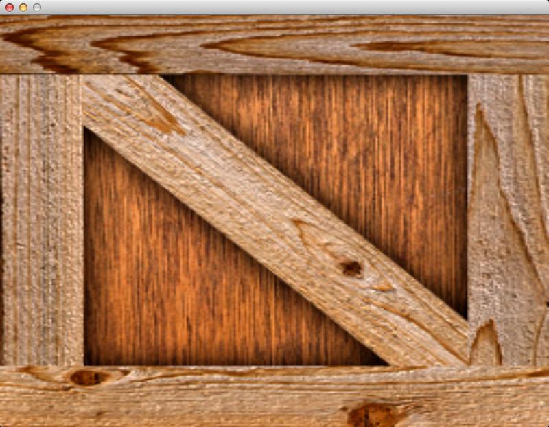
At this point, we have a couple of problems. Firstly, the cube is looking awfully 2D because we can only see one side of it. We need to “move the camera” so we are looking at the cube from a different angle. Secondly, something is wrong because the width and height of the cube should be the same, but the width is obviously larger than the height in the screenshot above. In order to fix these problems, we will have to learn a bit about matrices, and how they are used in 3D applications.
Clip Volume – The Default Camera
To understand how to make a “camera” in 3D, we must first understand the concept of the clip volume.
The clip volume is a cube. Whatever is inside the clip volume appears on the screen, and anything outside the clip volume is not visible.
The clip volume is a cube. Whatever is inside the clip volume appears on the screen, and anything outside the clip volume is not visible. It has the exact same size as the cube we made above. It ranges from -1 to +1 on the X, Y and Z axes. -X is left, +X is right, -Y is bottom, +Y is top, +Z is away from the camera, and -Z is toward the camera.
Because our cube is the exact same size as the clip volume, all we can see is the front side of the cube.
This also explains why our cube looks wider than it is tall. The window displays whatever is in the clip volume. The left and right edges of the window are -1 and +1 on the X axis, the bottom and top edges of the window are -1 and +1 on the Y axis. The clip volume gets stretched to fit the size of the viewport in the window, so our cube doesn’t look square anymore.
Moving The World While The Camera Stays Still
The clip volume can not be changed. It is always the same size, in the same position. So, instead of moving the camera, we must move the entire 3D scene so that it fits inside the clip volume cube correctly.
We want to make a camera that can move around, look in different directions, and maybe zoom in and out. However, the clip volume can not be changed. It is always the same size, and in the same position. So, instead of moving the camera, we must move the entire 3D scene so that it fits inside the clip volume cube correctly. For example, if we want to rotate the camera to the right, we actually rotate the whole world to the left. If we want to move the camera closer to the player, we actually move the player closer to the camera. This is how “cameras” work in 3D, they transform the entire world so that it fits into the clip volume and looks correct.
When you walk somewhere, it feels like the world is standing still, and you are moving. But you can also imagine that you are not moving at all, and the whole world is rotating underneath your feet, like you are on a treadmill. This is the difference between “moving the camera” and “moving the world.” Either way, it looks exactly the same to the viewer.
So how do we transform the 3D scene to fit into the clip volume? This is where we need to use matrices.
Implementing The Camera Matrix
Let’s implement the camera matrix first. As explained above “cameras” in 3D are just transformations that affect the whole 3D scene. Because a camera is a transformation, we can represent the camera as a matrix.
Firstly, we need to include a GLM header that will allow us to create different kinds of matrices.
#include <glm/gtc/matrix_transform.hpp>
Next, we need to update the vertex shader. We will make the camera matrix a
variable called camera, and every vertex will be multiplied by the camera
matrix. This is how we will transform the entire 3D scene. Every single vertex
will be transformed by the camera matrix. The new vertex shader looks like
this:
#version 150

uniform mat4 camera; //this is the new variable

in vec3 vert;
in vec2 vertTexCoord;

out vec2 fragTexCoord;

void main() {
    // Pass the tex coord straight through to the fragment shader
    fragTexCoord = vertTexCoord;

    // Transform the input vertex with the camera matrix
    gl_Position = camera * vec4(vert, 1);
}
Now we need to set the camera shader variable from our C++ code. At the
bottom of the LoadShaders function, we will add this code:
gProgram->use();

glm::mat4 camera = glm::lookAt(glm::vec3(3,3,3), glm::vec3(0,0,0), glm::vec3(0,1,0));
gProgram->setUniform("camera", camera);

gProgram->stopUsing();
The camera matrix isn’t going to change in this article, so we set it once, just after the shaders are created.
You can’t set shader variables unless the shader is in use, which is why we
have gProgram->use() and gProgram->stopUsing().
We are going to use the glm::lookAt function to create a camera matrix for
us. If you have used older versions of OpenGL, then you may have used the
gluLookAt function to achieve the same thing, but gluLookAt has been
removed from recent versions of OpenGL. The first argument glm::vec3(3,3,3)
is the position of the camera. The second argument glm::vec3(0,0,0) is what
the camera is looking at. The center of the cube is at (0,0,0) so that is where
we want the camera to look. The final argument glm::vec3(0,1,0) is the “up”
direction. We want the camera to be upright, so we set “up” to be the positive
direction of the Y axis. If the camera was upside down, or tilted sideways,
then this would be different.
After we’ve generated the camera matrix, we set the camera shader variable
with gProgram->setUniform("camera", camera);. The setUniform method
is part of the tdogl::Program class, and it calls glUniformMatrix4fv to set
the shader variable.
That’s it! We now have a functioning camera.
Unfortunately, if you run the program now you will see a completely black screen. This is because our camera matrix has transformed the vertices of the cube so that they are outside of the clip volume. As mentioned above, if it’s outside of the clip volume then it will not be visible. To make it visible again, we need to set use a projection matrix.
Implementing the Projection Matrix
Remember that the clip volume is only two units wide, high, and deep. Let’s say one unit is equivalent to one meter in our 3D scene. That means we can only see two meters infront of the camera, which isn’t very convenient.
What we need to do is expand the clip volume so that more of the 3D scene can fit inside it. We can’t change the size of the clip volume, but we can shrink the entire scene so that more of it fits into the clip volume. This shrinking is a transformation, so we can represent it as a matrix. This is basically what projection matrices are used for.
Let’s update the vertex shader to add the projection matrix variable. The updated shader looks like this:
#version 150

uniform mat4 projection; //this is the new variable
uniform mat4 camera;

in vec3 vert;
in vec2 vertTexCoord;

out vec2 fragTexCoord;

void main() {
    // Pass the tex coord straight through to the fragment shader
    fragTexCoord = vertTexCoord;

    // Apply camera and projection transformations to the vertex
    gl_Position = projection * camera * vec4(vert, 1);
}
In matrix multiplication, the transformations are applied from right to left, or from closest to farthest from the vertex.
Notice the order of the matrix multiplication:
projection * camera * vert. The camera transformation is
applied first, and the projection is applied second. In matrix multiplication,
the transformations are applied from right to left, or from closest to farthest
from the vertex.
Now let’s set the projection shader variable from the C++ code, the same way
we did for the camera variable. Inside the LoadShaders function, add the
following code just above the camera matrix code:
glm::mat4 projection = glm::perspective(glm::radians(50.0f), SCREEN_SIZE.x/SCREEN_SIZE.y, 0.1f, 10.0f);
gProgram->setUniform("projection", projection);
If you have used older versions of OpenGL then you may have used
gluPerspective to set the projection matrix, but gluPerspective has been
removed from recent versions of OpenGL. Fortunately glm::perspective can be
used as a replacement.
The first argument to glm::perspective is the “field of view” argument. This
is an angle, in radians, that specifies how wide the camera’s vision is.
Instead of specifying radians directly, I’m using the glm::radians to convert
50 degrees into radians. A large field of view means the camera can see a lot
of the scene, so the camera appears to be zoomed out. A small field of view
means the camera can only see a small portion of the scene, so it appears to be
zoomed in. The second argument is the “aspect” argument, which specifies the
aspect ratio of the view. This is almost always set to width/height of the
window. The second last argument is the “near plane.” The near plane is the
front of the clip volume, and the value 0.1 says that the near plane is 0.1
units away from the camera. Anything that is closer to the camera than 0.1 it
will not be visible. The near plane must be a value greater than zero. The last
argument is the “far plane”, which is the back of the clip volume. The value
10.0 says that the camera will display everything that is within 10 units of
the camera. Anything further than 10 units away will not be visible. Our cube
is about three units away, so it will be visible.
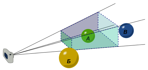
glm::perspective effectively fits a viewing frustum inside the clip
volume. A frustum is like a pyramid with the top cut off. The flat base of the
pyramid is the far plane. The flat part where the top has been cut off is the
near plane. The field of view is the skinniness or fatness of the frustum.
Anything inside the frustum will be displayed on the screen, and anything
outside will be hidden.
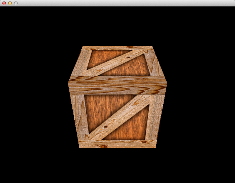
With the combination of the camera matrix and the projection matrix, we should be able to see the cube now. If you run the program at this point you will see this:
That looks… almost correct.
The cube looks square now, instead of rectangular. This is because of the
“aspect” argument of the call to glm::perspective, which corrects the aspect
ratio based on the width and height of the window.
Unfortunately, the screenshot above shows that some of the back sides of the cube are being rendered over the top of the front sides. We obviously don’t want this to happen, so we will enable depth buffering to fix the problem.
Depth Buffering
Depth buffering is one way to stop things in the background from being drawn over the top of things in the foreground.
By default, OpenGL draws over the top of whatever was previously drawn. If the back side of an object is drawn after the front, then the back will be drawn over the top of the front. Depth buffering is one way to stop things in the background from being drawn over the top of things in the foreground.
A preexisting pixel only gets overwritten if the new pixel is closer to the camera.
With depth buffering enabled, every pixel that is drawn knows how far away from the camera it is. It stores this distance as a number in the “depth buffer.” When you draw a pixel over an existing pixel, OpenGL will look at the depth buffer to determine which pixel is closer to the camera. If the new pixel being drawn is closer to the camera, it will overwrite the existing pixel. If the preexisting pixel is closer to the camera, then the new pixel being drawn is discarded. That is, a preexisting pixel only gets overwritten if the new pixel is closer to the camera. This is called “depth testing.”
Implementing Depth Buffering
Inside the AppMain function, after the call to glewInit, we add this code:
glEnable(GL_DEPTH_TEST);
glDepthFunc(GL_LESS);
This tells OpenGL to enable depth testing. The glDepthFunc call says that
pixels should be overwritten if the distance to the camera is less than the
existing pixel’s distance.
The last step is to clear the depth buffer every time we render a new frame. If
we didn’t do this then the old pixel distances would stay in the buffer, which
would ruin the rendering of the new frame. Inside the Render function we
change the glClear call to this:
glClear(GL_COLOR_BUFFER_BIT | GL_DEPTH_BUFFER_BIT);
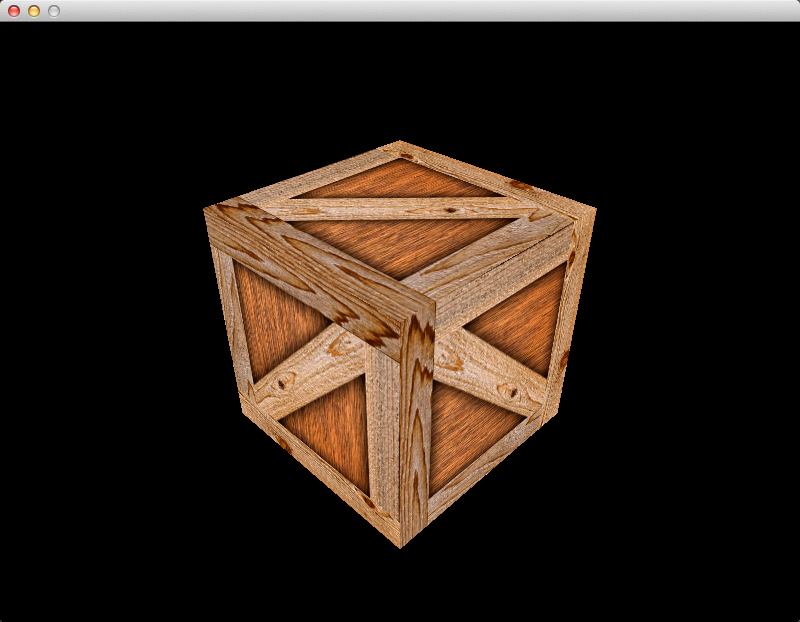
Finally, with depth buffering enabled, if you run the program the cube will be rendered correctly:
Rotating The Cube
Congratulations if you’ve made it this far! The final thing to implement is the spinning animation of the cube.
How are we going to implement the spinning? You guessed it: another matrix. The difference between this matrix and the others is that this matrix will change every frame. The other matrices are constant.
I’m going to call this new matrix the “model” matrix. In a normal 3D engine, each object has a different model matrix. The camera and the projection matrices are the same for the whole scene, but the model matrices are different for each object in the scene. The model matrix is used to put each object in the correct position (translation), to make the object face the correct direction (rotation), and to change the size of the object (scaling). We only have one object in our 3D scene, though, so we only have one model matrix.
Let’s add a model matrix variable to the vertex shader, like we did for the
camera and projection. The final version of the vertex shader looks like this:
#version 150

uniform mat4 projection;
uniform mat4 camera;
uniform mat4 model; //this is the new variable

in vec3 vert;
in vec2 vertTexCoord;

out vec2 fragTexCoord;

void main() {
    // Pass the tex coord straight through to the fragment shader
    fragTexCoord = vertTexCoord;

    // Apply all matrix transformations to vert
    gl_Position = projection * camera * model * vec4(vert, 1);
}
Notice the order of the matrix multiplication. The model matrix is the closest
one to the vert variable, which means the model matrix will be applied first,
then the camera, and lastly the projection.
Now we need to set the new model shader variable. Unlike the camera and
projection variables, the model variable needs to be set every frame, so we
will set it inside the Render function. Just after the call to
gProgram->use() add this code:
gProgram->setUniform("model", glm::rotate(glm::mat4(), glm::radians(45.0f), glm::vec3(0,1,0)));
We are using the glm::rotate function to create a rotation transformation
matrix. The first argument is an existing matrix to combine with the rotation
matrix. We don’t have an existing matrix to combine, so we just pass in a new
glm::mat4 object. The next argument is the angle of the rotation, or how
much to rotate. Let’s just set this to a constant 45° for now. The last
argument is the axis of the rotation. Imagine rotation as stabbing a skewer
through an object, and then twisting the skewer. The skewer is the axis, and
the angle is how much you twist it. In our case, we will use a vertical skewer,
so the cube will rotate like it is sitting on a flat table.
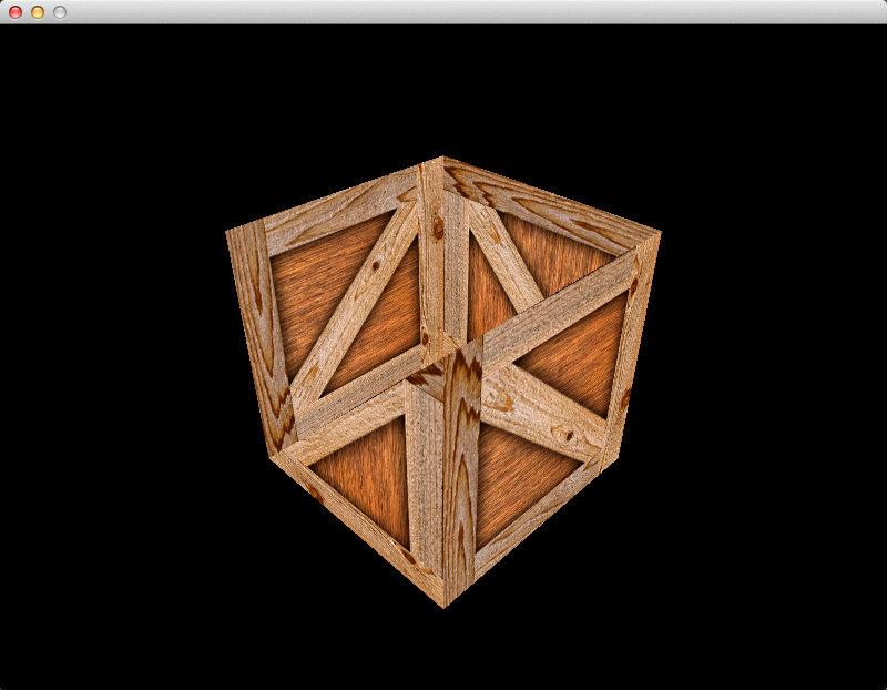
If you run the program now, you will see that the cube has been rotated:
It isn’t spinning yet, because the matrix doesn’t change – it is always set to rotate 45°. The last step is the change the rotation angle a little bit every frame.
Animation
First, let’s add a new global called gDegreesRotated.
GLfloat gDegreesRotated = 0.0f;
Every frame, we will slightly increase gDegreesRotated, and then we will use
it to calculate a new rotation matrix. This is how we will achieve animation.
What we want to do is update, draw, update, draw, update, draw, in that
pattern.
Let’s make a function called Update that will slightly increase the
gDegreesRotated every time it is called:
void Update() {
    //rotate by 1 degree
    gDegreesRotated += 1.0f;

    //don't go over 360 degrees
    while(gDegreesRotated > 360.0f) gDegreesRotated -= 360.0f;
}
Now we need to call the Update function every time we draw a new frame. Let’s
add it to the loop in AppMain, just before the call to Render.
while(glfwGetWindowParam(GLFW_OPENED)){
    // process pending events
    glfwPollEvents();

    // update the rotation animation
    Update();

    // draw one frame
    Render();
}
Now we just have to recalculate the model matrix based on the gDegreesRotated
variable. Inside the Render function we’ll modify the code to set the model
matrix:
gProgram->setUniform("model", glm::rotate(glm::mat4(), glm::radians(gDegreesRotated), glm::vec3(0,1,0)));
The only difference is that we are using the variable gDegreesRotated instead
of a constant 45°.
If you run the program now you should see a nice, smooth spinning animation of the cube. The only problem is that the spinning speed is tied to how many frames per second (FPS) we can render. If the FPS goes up, then the cube spins faster. If the FPS goes down, the cube spins more slowly. This isn’t ideal. A program should update correctly regardless of how many FPS it is running at.
Time-based Animation
To make the program run correctly, independent of FPS, the animation should be
updated per second, not per frame. The simplest way to do this is to count
the number of seconds elapsed since the last update, and update accordingly.
Let’s change the Update function so that it takes an argument called
secondsElapsed:
void Update(float secondsElapsed) {
    const GLfloat degreesPerSecond = 180.0f;
    gDegreesRotated += secondsElapsed * degreesPerSecond;
    while(gDegreesRotated > 360.0f) gDegreesRotated -= 360.0f;
}
This will make the cube spin at a constant 180° per second, no matter what the frame rate is.
In the AppMain loop, we need to calculate how many seconds have elapsed since
the last update. The new loop looks like this:
double lastTime = glfwGetTime();
while(glfwGetWindowParam(GLFW_OPENED)){
    // process pending events
    glfwPollEvents();

    // update the scene based on the time elapsed since last update
    double thisTime = glfwGetTime();
    Update((float)(thisTime - lastTime));
    lastTime = thisTime;

    // draw one frame
    Render();
}
glfwGetTime returns the number of seconds elapsed since the program started
running.
We use a variable called lastTime to remember when the last update happened.
Each iteration of the loop, we get the current time in the variable thisTime.
The time elapsed since the last update is thisTime - lastTime. After the
update is finished, we set lastTime = thisTime so that the next iteration
through the loop will work.
This is a simple way to update based on time. There is a better way to do time-based updates, but it is more complicated and we don’t need it yet.
Future Article Sneak Peek
In the next article we will be make the tdogl::Camera class, which will allow
us to have a first-person-shooter-style camera that can move around with the
keyboard, look in different directions with the mouse, and zoom in and out with
the mouse wheel.
Additional Resources
- Tutorial 3 : Matrices is a great explanation of matrices from opengl-tutorial.org
- Scaling, rotation, translation, and transformation matrices on Wikipedia
- Basic 3D Math: Matrices
- Homogeneous coordinates by Lawrence Kesteloot
- Viewing chapter of the OpenGL red book. Uses old version of OpenGL in code examples, but the theory is still the same.
- GLM code samples andmanual (pdf)
- Z-buffering (depth buffering) on Wikipedia
- Overlap and Depth Buffering section of the Learning Modern 3D Graphics Programming book
- Fix Your Timestep! by Glenn Fiedler