In this article, we will be adding directional lights, spotlights, and allowing for multiple lights instead of just one. This is the final article on lighting – at least for a while.
Accessing The Code
Download all the code as a zip from here: https://github.com/tomdalling/opengl-series/archive/master.zip
All the code in this series of articles is available from github: https://github.com/tomdalling/opengl-series. You can download a zip of all the files from that page, or you can clone the repository if you are familiar with git.
This article builds on the code from the previous article.
The code for this article can be found in the
source/08_even_more_lighting
folder. On OS X, open the opengl-series.xcodeproj file in the
root folder, and select the target that corresponds with this article. On
Windows, open the opengl-series.sln file in Visual Studio 2013,
and open the project that corresponds with this article.
The project includes all of its dependencies, so you shouldn't have to install or configure anything extra. Please let me know if you have any issues compiling and running the code.
Directional Lights
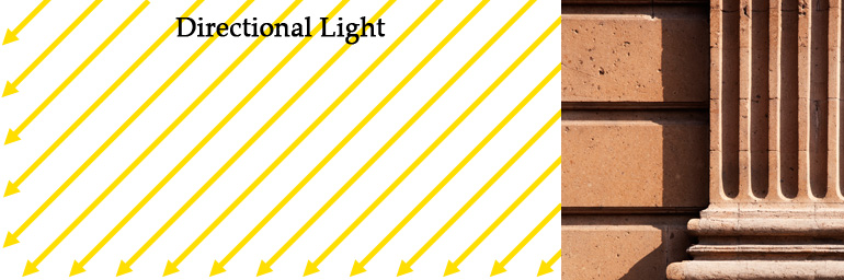
Directional lights are lights that shine in a single, uniform direction. That is, all rays of light are parallel to each other. Pure directional lights do not exist (except maybe lasers?) but they are often used in computer graphics to imitate strong light sources that are very far away, such as the Sun. The Sun radiates light in all directions, like a point light. Over an enormous distance, however, the tiny fraction of light rays that make it to earth appear to be almost parallel.
Directional lights are implemented such that they ignore attenuation.
As we saw in the previous article on homogeneous coordinates, directional lights can be thought of as point lights that are infinitely far away. This causes an unfortunate interaction with attenuation. Attenuation is the reduction of light intensity over distance – the greater the distance, the dimmer the light is. If there is even the tiniest amount of attenuation, over an infinite distance the light becomes infinitely dim (i.e. invisible). For this reason, directional lights are implemented such that they ignore attenuation. This kind-of makes sense if we’re using directional lights to represent the Sun, because the sunlight we see here on Earth doesn’t appear to be attenuated. That is, sunlight doesn’t appear to get dimmer as it gets closer to the ground.
We can represent the direction of a directional light with a homogeneous coordinate by setting $$W = 0$$.
Unlike point lights, directional lights do not need a position coordinate. A directional light only needs a single 3D vector that represents the direction of all the rays of light. However, the GLSL lighting code in our shader expects every light to have a position. Luckily, we can represent the direction of a directional light with a homogeneous coordinate by setting $$W = 0$$. As explained in the previous article on homogeneous coordinates, when $$W = 0$$ in a 4D coordinate, it represents the direction towards a point that is infinitely far away. So if the coordinate represents the direction towards the Sun, we can just negate it to produce the direction away from the Sun, which is the direction of the light rays. Using this method of representing directional lights inside the position vector, we could have code that looks like this:
uniform vec4 lightPosition;

// check if this is a directional light
if(lightPosition.w == 0.0) {
  // it is a directional light.
  // get the direction by converting to vec3 (ignore W) and negate it
  vec3 lightDirection = -lightPosition.xyz
} else {
  // NOT a directional light
}
As an example, let’s say that lightPosition coordinate is $$(1, 0, 0, 0)$$,
which represents a point infinitely far away down the positive X axis. If we
take the $$X$$, $$Y$$, and $$Z$$ values then negate them, we get $$(-1, 0,
0)$$, which indicates that the light is shining down the negative X axis.
The GLSL lighting code we implemented in the previous article uses the
direction from the surface to the light (in a variable named surfaceToLight),
so we don’t actually need to negate anything. The GLSL for directional lights
in this article looks like this:
vec3 ApplyLight(Light light, vec3 surfaceColor, vec3 normal, vec3 surfacePos, vec3 surfaceToCamera) {
    vec3 surfaceToLight;
    float attenuation = 1.0;
    if(light.position.w == 0.0) {
        //directional light
        surfaceToLight = normalize(light.position.xyz);
        attenuation = 1.0; //no attenuation for directional lights
    } else {
        // NOT directional light
        //... (code ommited)
    }

    // the rest of the lighting calculation
    //... (code ommited)
}
Spotlights
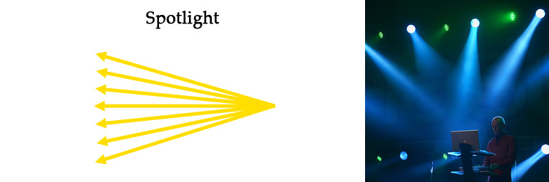
The final type of light we will be implementing is spotlights. Spotlights are very similar to point lights, except that instead of radiating light out in all directions, the light rays are restricted to a cone shape. The light rays are not parallel like directional lights, but they do shine out in a general direction. Think of a flashlight. There is a light bulb in there that acts like a point light, but there is also a reflective curved surface that restricts where the light can shine.
We will model spotlights as point lights with a cone restriction.
We will model spotlights as point lights with a cone restriction. Everything
that applies to point lights also applies to spotlights, except for two
extra variables: the direction of the cone, and the angle of the cone. Here
is the definition of the Light struct for this article:
uniform struct Light {
   vec4 position;
   vec3 intensities;
   float attenuation;
   float ambientCoefficient;
   float coneAngle;    // new
   vec3 coneDirection; // new
};
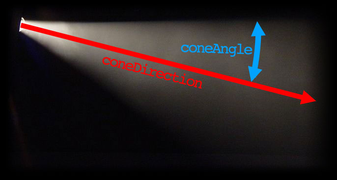
There are two new variables that were added in order to implement spotlights:
coneAngle and coneDirection. The coneDirection variable is the direction
from the point of the cone, through the center of the cone. The coneAngle
variable is the angle between the center and the side of the cone, in degrees.
If the pixel is outside of the cone, then we set the attenuation factor to zero.
The implementation is fairly simple. For every pixel, we check whether it is inside or outside of the light cone. If it’s inside, we continue with the lighting calculations as we normally would. If the pixel is outside of the cone, then we set the attenuation factor to zero, which will make the light ray invisible. Here is the GLSL that implements the cone restriction:
float lightToSurfaceAngle = degrees(acos(dot(-surfaceToLight, normalize(light.coneDirection))));
if(lightToSurfaceAngle > light.coneAngle){
    attenuation = 0.0;
}
The first line is pretty dense, so let me explain it by break it down into smaller steps:
// 1. Get the direction for the center of the cone. The `normalize`
//    function is called just in case `light.coneDirection` isn't
//    already a unit vector.
vec3 coneDirection = normalize(light.coneDirection);

// 2. Get the direction of the ray of light. This is the opposite
//    of the direction from the surface to the light.
vec3 rayDirection = -surfaceToLight;

// 3. Get the angle between the center of the cone and the ray of light.
//    The combination of `acos` and `dot` return the angle in radians, then
//    we convert it to degrees.
float lightToSurfaceAngle = degrees(acos(dot(rayDirection, coneDirection)))

// 4. Check if the angle is outside of the cone. If so, set the attenuation
//    factor to zero, to make the light ray invisible.
if(lightToSurfaceAngle > light.coneAngle){
  attenuation = 0.0;
}
These cone restrictions are going to be applied to all non-directional lights, which
includes point lights. To stop the restrictions from applying to a point light,
all we have to do is set coneAngle to 180.0, which means that light can
shine in all directions.
Multiple Lights
We are just refactoring the existing fragment shader code and adding a loop.
The fragment shader for the previous article only implemented a single light so let’s replace the single light with an array of lights. Then we can loop over them in the fragment shader, and apply them all to the scene. We aren’t really implementing anything new here. We are just refactoring the existing fragment shader code and adding a loop.
The first step is to remove the single light uniform from the fragment shader, and replace it with an array. This is the old GLSL from the previous article:
// code from previous article (a single light)
uniform struct Light {
   vec3 position;
   vec3 intensities; //a.k.a the color of the light
   float attenuation;
   float ambientCoefficient;
} light;
And this is the new code, with an array of lights:
// array of lights
#define MAX_LIGHTS 10
uniform int numLights;
uniform struct Light {
   vec4 position;
   vec3 intensities; //a.k.a the color of the light
   float attenuation;
   float ambientCoefficient;
   float coneAngle;
   vec3 coneDirection;
} allLights[MAX_LIGHTS];
This implementation is very similar to the lighting implementation in the old
fixed-function pipeline of OpenGL. There is a maximum number of lights, set
in the MAX_LIGHTS constant. Then there is an uniform variable that
hold the array of lights, called allLights. Lastly, there is a uniform
variable that holds the number of lights we are actually using, called
numLights.
The next step is to refactor the GLSL code so that it loops over the array.
We extract all the lighting code into a function called ApplyLight, which
does the entire lighting calculation for a single light. Here is the
GLSL for the ApplyLight function:
vec3 ApplyLight(Light light, vec3 surfaceColor, vec3 normal, vec3 surfacePos, vec3 surfaceToCamera) {
    vec3 surfaceToLight;
    float attenuation = 1.0;
    if(light.position.w == 0.0) {
        //directional light
        surfaceToLight = normalize(light.position.xyz);
        attenuation = 1.0; //no attenuation for directional lights
    } else {
        //point light
        surfaceToLight = normalize(light.position.xyz - surfacePos);
        float distanceToLight = length(light.position.xyz - surfacePos);
        attenuation = 1.0 / (1.0 + light.attenuation * pow(distanceToLight, 2));

        //cone restrictions (affects attenuation)
        float lightToSurfaceAngle = degrees(acos(dot(-surfaceToLight, normalize(light.coneDirection))));
        if(lightToSurfaceAngle > light.coneAngle){
            attenuation = 0.0;
        }
    }

    //ambient
    vec3 ambient = light.ambientCoefficient * surfaceColor.rgb * light.intensities;

    //diffuse
    float diffuseCoefficient = max(0.0, dot(normal, surfaceToLight));
    vec3 diffuse = diffuseCoefficient * surfaceColor.rgb * light.intensities;

    //specular
    float specularCoefficient = 0.0;
    if(diffuseCoefficient > 0.0)
        specularCoefficient = pow(max(0.0, dot(surfaceToCamera, reflect(-surfaceToLight, normal))), materialShininess);
    vec3 specular = specularCoefficient * materialSpecularColor * light.intensities;

    //linear color (color before gamma correction)
    return ambient + attenuation*(diffuse + specular);
}
The ApplyLight function takes a single light as an argument, but it also
takes some arguments that describe the surface that is being lit:
surfaceColor, normal, surfacePos, and surfaceToCamera. Because all the
lights are acting upon the same surface, we calculate these surface-related
variables once, and pass them in as arguments for every light.
With all the lighting code extracted into a function, we can loop through
all the lights. For each light, we call ApplyLight and add all the
results together to get the color for the surface:
vec3 linearColor = vec3(0);
for(int i = 0; i < numLights; ++i){
    linearColor += ApplyLight(allLights[i], surfaceColor.rgb, normal, surfacePos, surfaceToCamera);
}
C++ Code Changes
The changes to the C++ code are mainly just mirrors of the GLSL changes.
The Light struct changes slightly, to accommodate directional lights and
spotlights. The position element changes from a glm::vec3 to a
glm::vec4, and we add the two spotlight cone variables coneDirection
and coneAngle.
struct Light {
    glm::vec4 position;
    glm::vec3 intensities; //a.k.a. the color of the light
    float attenuation;
    float ambientCoefficient;
    float coneAngle; // new
    glm::vec3 coneDirection; // new
};
In the globals, we change the single light to a std::vector of lights:
// Light gLight; // used to be this in previous article
std::vector<Light> gLights;
In the RenderInstance function, we now have to loop through all the
lights when we set the uniforms:
shaders->setUniform("numLights", (int)gLights.size());

for(size_t i = 0; i < gLights.size(); ++i){
    SetLightUniform(shaders, "position", i, gLights[i].position);
    SetLightUniform(shaders, "intensities", i, gLights[i].intensities);
    SetLightUniform(shaders, "attenuation", i, gLights[i].attenuation);
    SetLightUniform(shaders, "ambientCoefficient", i, gLights[i].ambientCoefficient);
    SetLightUniform(shaders, "coneAngle", i, gLights[i].coneAngle);
    SetLightUniform(shaders, "coneDirection", i, gLights[i].coneDirection);
}
This uses a function called SetLightUniform, which constructs the uniform names
based on the struct element and the index (e.g. "allLights[2].coneAngle").
template <typename T>
void SetLightUniform(tdogl::Program* shaders, const char* propertyName, size_t lightIndex, const T& value) {
    std::ostringstream ss;
    ss << "allLights[" << lightIndex << "]." << propertyName;
    std::string uniformName = ss.str();

    shaders->setUniform(uniformName.c_str(), value);
}
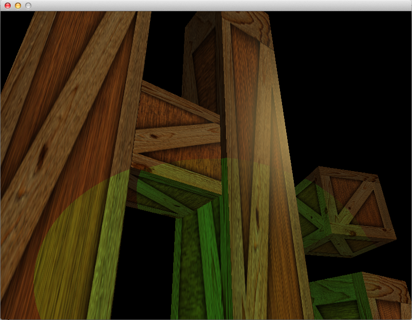
In AppMain, we create a spotlight and a directional light:
// setup lights
Light spotlight;
spotlight.position = glm::vec4(-4,0,10,1);
spotlight.intensities = glm::vec3(2,2,2); //strong white light
spotlight.attenuation = 0.1f;
spotlight.ambientCoefficient = 0.0f; //no ambient light
spotlight.coneAngle = 15.0f;
spotlight.coneDirection = glm::vec3(0,0,-1);

Light directionalLight;
directionalLight.position = glm::vec4(1, 0.8, 0.6, 0); //w == 0 indications a directional light
directionalLight.intensities = glm::vec3(0.4,0.3,0.1); //weak yellowish light
directionalLight.ambientCoefficient = 0.06;

gLights.push_back(spotlight);
gLights.push_back(directionalLight);
And in the Update function, we make the key 1 change the position and
direction of the spotlight:
//move light
if(glfwGetKey('1')){
    gLights[0].position = glm::vec4(gCamera.position(), 1.0);
    gLights[0].coneDirection = gCamera.forward();
}
Further Lighting
At this point, we have basically implemented all the lighting options that were available in the old fixed-function API of OpenGL. We went a step further by implementing per-fragment lighting instead of per-vertex lighting, but there are many more improvements that we haven’t covered. Lighting is a huge subject, so for now I’m just going to give a brief overview of a few advanced lighting topics.
Blinn-Phong
Our lighting in this series is an implemention of the Phong reflection model. There is a slightly better version of this algorithm, called the Blinn-Phong reflection model. Blinn-Phong is a bit more accurate, and has slightly better performance too.
Fancier Spotlights
The spotlight implementation in this article is very basic. It could be improved by softening the hard edges in GLSL using the mix function. You could also sample a flashlight texture to stop the light from looking so circular and flat.
Deferred Rendering
The way we have implemented lighting is known as forward rendering, and there are a couple of annoying issues associated with it. Firstly, there is a limit to the number of lights we can have. Secondly, every pixel that gets drawn requires calculations for every light – even if there are lights that do not affect the pixel – which can be a performance issue. Ideally, we want to be able to have thousands of lights with decent performance. To address these issues, we could use deferred rendering.
Deferred rendering is a technique where you split rendering up into multiple passes. The first pass renders geometry without any lights. In subsequent passes, the lights are rendered one at a time. Lighting happens to every pixel, instead of every fragment, which improves performance. You are also able to restrict which pixels each light affects to further improve performance.
In summary, deferred rendering allows lots of lights with decent performance, but it is more complicated than forward rendering.
Shadows
Despite that fact that everyone loves the look of them, nice shadows are a huge can of worms, and can be extremely complicated. All the following techniques are way more complicated than what this series of articles has covered so far.
Shadow maps are probably the simplest technique, but the resulting shadows can be weird and pixelated.
Shadow volumes give pixel-perfect results, but they require complicated processing on your geometry, which is slow.
When the light and the geometry are both static, then lightmaps are accurate and have good performance.
Don’t even get me started on ambient occlusion.
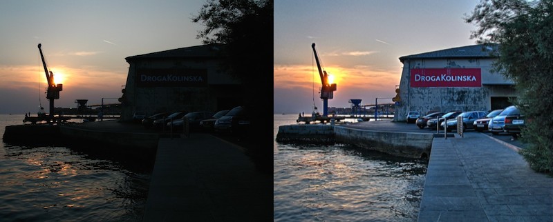
High-dynamic-range (HDR)
.jpg)
Notice how the colors from all the lights are added together in our fragment shader. The RGBA values are supposed to be within the 0.0 to 1.0 range, so what happens if there are lots of lights, and the sum ends up being greater than 1.0? The colors would get clamped, and look weird. Also, if the lights are too dim, the whole scene could look basically black, with no detail. High-dynamic-range (HDR) rendering can help to fix these problems.
The human eye adjusts depending on the brightness of what it’s looking at. If you are in a dark room for long enough, your pupils dilate to allow more light to reach your retina, which makes the room seem brighter. If you walk outside into bright sunlight, the opposite happens, so that you don’t go blind from the intense light. HDR rendering sort of imitates how your eye works, in order to keep the details visible in very dark and very bright scenes. RGB values are allowed to go above 1.0 during lighting calculations, then the values are later rescaled so that they fit nicely within the 0.0–1.0 range.
Subsurface Scattering

Light doesn’t just reflect off of surfaces, it can travel through them too. When light penetrates a surface, it changes the color of that surface. Rendering this color change is called subsurface scattering.
Even though skin looks fairly opaque, subsurface scattering is generally used for realistic rendering of human skin. Without it, skin tends to look like painted plastic.
Emissive Surfaces
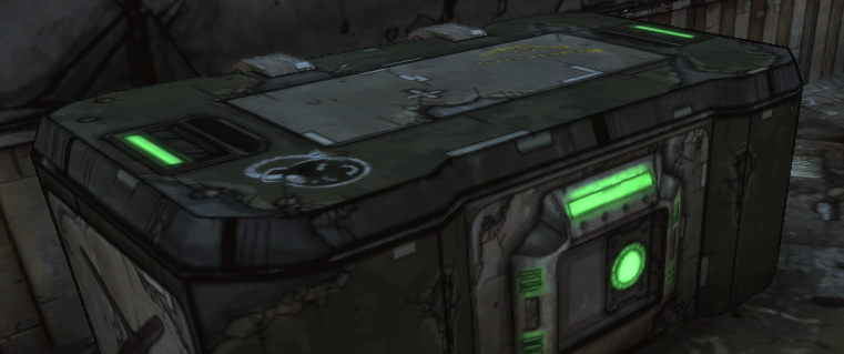
In our implementation, only lights can illuminate a surface. Some surfaces, however, provide their own illumination, which makes it look like they are glowing. Think of a firefly, glow-in-the-dark stickers, or those weird glowing mushrooms.
Emissive lights are pretty easy to implement in OpenGL. Send an extra color uniform to the shaders, along with the materials texture and shininess, and add that color to the final color. Alternatively, you can send an extra texture instead of a single color.
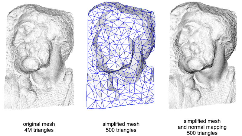
Normal Mapping
3D meshes have limits to the number of vertices they can contain, due to performance. Making a surface rough or bumpy with geometry can take a lot of vertices, so normal maps are often used instead. Normal maps can be used to make an angular-looking 3D model look less angular, and more realistic.
A normal map is a texture that affects the surface normal. It is like the surface texture that we have implemented, except it contains XYZ vectors instead of RGB colors. The surface normal is an important part of the lighting calculations, and it affects the brightness of each pixel.
Conclusion
That wraps up our lighting implementation for now. After adding directional lights and spotlights, we have recreated the functionality that was available in the old fixed-function OpenGL API.